Loomo SDK
Loomo SDK
Things to Note
Before using Loomo's SDK, please be aware of the following:
Connecting to Service
Before using the functionality provided by each SDK, it is required to call bindService() first. The result is returned via ServiceBinder. After using the SDK, please call unbindService().
  ServiceBinder.BindStateListener mBindStateListener = new ServiceBinder.BindStateListener() {
        @Override
        public void onBind() {
            mBind = true;
        }

        @Override
        public void onUnbind(String reason) {
            mBind = false;
        }
    };
Timestamp
In the robot system, to coordinate between the various components, timestamps need to be added to all of the collected information. In the base SDK, the "StampedData" interface is provided. All data types inherit this interface, and you can get the timestamp of the data by calling the getTimeStamp() method.
Note: The time provided in the current Vision SDK is the time from the RealSense Module, not the time from the main system.
Background Service Limitation
By design, Loomo only supports binding to services that run in the foreground. Thus, when the applications are switched to the background, the SDK automatically disconnects the service.
The services that need to be used in the foreground are:
- Vision
- Speech
- Locomotion
- Interaction
Robot States
Loomo can transform between a robot and a self-balancing vehicle.
When Loomo transforms into a self-balancing vehicle, the system broadcasts an intent action indicating this event. At this moment, Vision Service stops image streaming, Voice Service stops wakeup/recognition, and Locomotion Service rejects all control instructions. The screen goes off and the system suspends in a few seconds.
When the self-balancing vehicle transforms into a robot, the system will resume and broadcast another intent action, the screen turns on and the services work again.
Applications can receive these intent actions by BroadcastReceiver, the actions are defined in RobotAction:
String SBV_MODE = "com.segway.robot.action.TO_SBV";
String ROBOT_MODE = "com.segway.robot.action.TO_ROBOT";
Robot Event Broadcast
Apps can choose to receive broadcast messages from events as they occur.
RobotAction.PowerEvent
BATTERY_CHANGED
value "com.segway.robot.action.BATTERY_CHANGED"
This message is broadcast whenever the robot battery level changes.
POWER_DOWN
value "com.segway.robot.action.POWER_DOWN"
This message is broadcast when the robot is about to power down.
POWER_BUTTON_PRESSED
value "com.segway.robot.action.POWER_BUTTON_PRESSED"
This message is broadcast when the tablet power button is pressed.
POWER_BUTTON_RELEASED
value "com.segway.robot.action.POWER_BUTTON_RELEASED"
This message is broadcast when the power button is released.
RobotAction.TransformEvent
SBV_MODE
value "com.segway.robot.action.TO_SBV"
This message is broadcast when Loomo starts to enter SBV mode. It indicates the beginning of a transformation.
ROBOT_MODE
value "com.segway.robot.action.TO_ROBOT"
This message is broadcast when Loomo starts to enter robot mode. It indicates the beginning of a transformation.
RobotAction.HeadEvent
PITCH_LOCK
value "com.segway.robot.action.PITCH_LOCK"
This message is broadcast when the pitch of Loomo's head is locked. In this state, Loomo's head is faced down and locked. It happens when Loomo enters SBV mode.
PITCH_UNLOCK
value "com.segway.robot.action.PITCH_UNLOCK"
This message is broadcast when the pitch of Loomo's head is unlocked. It happens when Loomo enters robot mode.
YAW_LOCK
value "com.segway.robot.action.YAW_LOCK"
This message is broadcast when the yaw of Loomo's head is locked. In this state, Loomo's head is facing left and locked. It happens when Loomo enters SBV mode.
YAW_UNLOCK
value "com.segway.robot.action.YAW_UNLOCK"
This message is broadcast when the yaw of Loomo's head is unlocked.It happens when Loomo enters SBV mode.
RobotAction.ActionEvent
STEP_ON
value "com.segway.robot.action.STEP_ON"
This message is broadcast when the pressure sensor detects a certain amount of weight on its pedals.
STEP_OFF
value "com.segway.robot.action.STEP_OFF"
This message is broadcast when the pressure sensor no longer detects weight on its pedals.
LIFT_UP
value "com.segway.robot.action.LIFT_UP"
This message is broadcast when Loomo is lifted off the ground.
PUT_DOWN
value "com.segway.robot.action.PUT_DOWN"
This message is broadcast when Loomo is put on the ground. This event is triggered by releasing the inside of the lift handle.
PUSHING
value "com.segway.robot.action.PUSHING"
This message is broadcast when the user touches the head-touch bar. The movement of Loomo is then fully guided by the person holding the head of the robot and any motion-related API calls will be ignored.
PUSH_RELEASE
value "com.segway.robot.action.PUSH_RELEASE"
This message is broadcast when the user no longer touches the head-touch bar. The movement of Loomo returns to its previous state.
RobotAction.BaseEvent
BASE_LOCK
value "com.segway.robot.action.BASE_LOCK"
This message is broadcast when the base of Loomo is locked. The wheel motor will power down, and Loomo will no longer balance itself. It must be put on the floor. This event usually happens during OTA updating.
BASE_UNLOCK
value "com.segway.robot.action.BASE_UNLOCK"
This message is broadcast when the base of the robot is unlocked. The wheel motor will power on again. Users can let the robot stand up, and it will balance itself. This event usually happens when the OTA has been updated.
STAND_UP
value "com.segway.robot.action.STAND_UP"
This message indicates the base of the robot is upright.
VISION
Loomo is equipped with a powerful Intel RealSense camera. Developers can use it to capture both color and depth images. For more information about Intel RealSense, see:
http://www.intel.com/content/www/us/en/architecture-and-technology/realsense-overview.html
The vision service is used to control the initialization and configuration of the Intel RealSense camera, allowing developers to retrieve live image data. 2 Mega pixel RGB, infrared, and 3D depth images are supported.
To use the vision service, you need to initialize the Vision instance and bind to the service. See the following sample code:
mVision = Vision.getInstance();
mVision.bindService(this, mBindStateListener);
Because the vision service cannot set the captured image parameters, such as image size, pixel format, frame rate, etc., the application needs to request these parameters in order to display the images on Loomo's screen. Therefore, after binding to the vision service, type the following code:
StreamInfo[] infos = mVision.getActivatedStreamInfo();The currently supported output formats are:
| Image Type | Resolution | Pixel format |
|---|---|---|
| Depth Image | 320x240 | Z16 |
| Color Image | 640x480 | ARGB8888 |
You can get the images captured by the Intel RealSense device by calling startListenFrame and setting the callback:
private Bitmap mBitmap = Bitmap.createBitmap(640, 480, Bitmap.Config.ARGB_8888);

mVision.startListenFrame(StreamType.DEPTH, new Vision.FrameListener() {
    @Override
    public void onNewFrame(int streamType, Frame frame) {
          mBitmap.copyPixelsFromBuffer(frame.getByteBuffer());
    }
});
Fisheye Camera
Loomo comes with a fisheye camera, with super-wide FOV, to implement visual simultaneous localization and mapping, which our team has proven to be useful and effective.
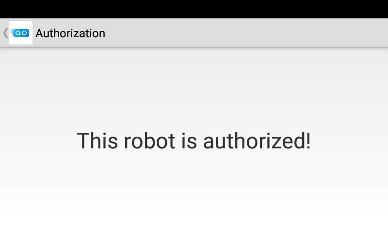
At the moment, the fisheye camera is not openly accessible to the public. However, if you would like to use it, please follow the instructions below to apply for authorization.
First, e-mail us at service@loomo.com and include all of the serial numbers of the Loomos that you wish to have access to the fisheye camera. You can get Loomo's serial number from Settings->About Tablet->Status.

Then, after having received your request, we will send you a contract describing the scope of your authority with respect to the fisheye camera. After you agree to the terms of the contract, we will send you an APK. Once the APK is installed,Loomo will have access to the fisheye camera.
The following code allows you to get image streaming from the fisheye camera.
private Bitmap mFishEyeBitmap = Bitmap.createBitmap(640, 480, Bitmap.Config.ALPHA_8);

mVision.startListenFrame(StreamType.FISH_EYE, new Vision.FrameListener() {
    @Override
    public void onNewFrame(int streamType, Frame frame) {
          mFishEyeBitmap.copyPixelsFromBuffer(frame.getByteBuffer());
    }
});Note: If you call the fisheye method without authorization, the following exception will occur: java.lang.IllegalStateException: This robot hasn't be authorized!
Detection-tracking system(DTS)
The detection-tracking system (DTS) is a vision-based system that implements upper body detection and tracking.
Using the DTS together with other Loomo-equipped services, one can easily design and implement a person-tracking-and-following application.
Note: There are a few known issues with the DTS. When tracking somebody, in some cases, the Person instance returned by the onPersonTracked callback will produce the wrong distance. The optimal distance from Loomo is between 0.35 meters and 5 meters.
To use the DTS, please get the Vision instance and bind to the VisionService first. Then get the DTS instance from Vision.
Before detecting or tracking, choose the video source mode.
In the camera mode, VisionService will open and manage the platform camera. By calling the start() method, the DTS module will start to work. And when you do not need to use DTS, call stop().
The following code demonstrates how to use the DTS:
// get the DTS instance
DTS dts = mVision.getDTS();

// set video source
dts.setVideoSource(DTS.VideoSource.CAMERA);

// set preview surface
Surface surface = new Surface(autoDrawable.getPreview().getSurfaceTexture());
dts.setPreviewDisplay(surface);

// start dts module
dts.start();

// detect person in 3 seconds
Person[] persons = dts.detectPersons(3 * 1000 * 1000)

// track the first person(if there is a person detected)
dts.startPersonTracking(persons[0], 10 * 1000, new PersonTrackingListener {...})

// stop person tracking
dts.stopPersonTracking()

// stop dts module
dts.stop();
DTS will automatically try to find a person in the center of the platform image if null is passed to startPersonTracking.
Obstacle avoidance APIs are also released but the robot may run into people or other obstacles sometimes. Always be on the look-out when testing the FollowMe sample. The only difference is the starting method.
// Loomo will detect obstacles and avoid them
dts.startPlannerPersonTracking(null, mPersonTrackingProfile, 60 * 1000 * 1000, new PersonTrackingWithPlannerListener{...});
To preview and get raw RealSense data, please see the Vision sample:
Download the sample code of the Vision Sample.
To use DTS and implement a person-following Loomo application, please see the FollowMe sample:
Download the sample code of the FollowMe Sample.
See the detailed SDK document.
SPEECH
Loomo is equipped with an advanced 5-channel microphone array, which localizes the sound source while providing voice wake-up and high-accuracy speech recognition. Speech is divided into two modules:
- Recognition module: Responsible for voice wake-up, speech recognition, and customized grammar. You can configure GrammarConstraint to recognize different contents in different scenarios. Besides speech recognition, the Recognition service also supports beamforming voice recording which can record voices from a distance and effectively reduce background noise.
- Speaker module: Responsible for text-to-speech conversion.
Recognition
To activate Loomo's speech recognition service, you need to wake up the device with wake-up words such as: "Ok Loomo," "Hello Loomo," "Loomo Loomo," "Loomo transporter," "Hi loomo," and "Hey Loomo."
And in order to create meaningful speech commands, you need to create speech phrases/sentences for Loomo to listen for. In the Recognition SDK, Slot and GrammarConstraint are used to assist Loomo in understanding speech commands:
- Slot: a word or a group of words.
- GrammarConstraint: Speech syntax that accepts one or more Slots. The words in each Slot can be combined to form a sentence.
See the following example of a GrammarConstraint:
GrammarConstraint:<Slot1> [<Slot2>] <Slot3>
Slot1: turn/walk
Slot2: to the
Slot3: left/right
Note: In this example, [] is for optional content.
Note: If you add more than two GrammarConstraints, only the latest two can work well and the amount is limited since initialization is time-consuming.
In the above example, the following statements can be recognized:
- turn left
- turn right
- turn to the left
- turn to the right
- walk left
- walk right
- walk to the left
- walk to the right
In the Recognition Service, you can use the returned values of the onRecognitionResult and the onRecognitionError callback in RecognitionListener for continuous recognition. This design enables developers to replace the previously recognized commands with new ones to achieve accurate continuous recognition:

See the following sample code:
Before using it, you need to initialize and bind to the service:
Recognizer is the class from which to get the instance for the Recognition SDK. After instantiating it, you need to initialize and bind the service:
mRecognizer = Recognizer.getInstance();

//bind the recognition service.
mRecognizer.bindService(MainActivity.this, mRecognitionBindStateListener);
Get the current language:
mRecognitionLanguage = mRecognizer.getLanguage();Note: The current version only supports Mandarin and English. Please note, mixed languages cannot be recognized. Language is determined in the system language settings.
Add the previously generated GrammarConstraint:
mRecognizer.addGrammarConstraint(mTwoSlotGrammar);Begin the wake-up and recognition, send the instance of WakeupListener and RecognitionListener, and get the state of wake-up and recognition:
mRecognizer.startRecognition(mWakeupListener, mRecognitionListener);See the sample code and SDK document for more information about WakeupListener and RecognitionListener.
Note:: There are several words reserved by Loomo that cannot be used as recognition words.
"loomo loomo", "ok loomo", "hey loomo", "yo loomo", "hello loomo", "hi loomo", "come here", "come to me", "open camera", "turn on the camera", "close camera", "turn off the camera", "follow me", "stop follow me", "stop following"
Speaker
Speaker is responsible for converting the text to speech. Before using it, you need to initialize the Speaker instance and bind to the service:
mSpeaker = Speaker.getInstance();

//bind the speaker service.
mSpeaker.bindService(MainActivity.this, mSpeakerBindStateListener);
Get the current language:
mSpeakerLanguage = mSpeaker.getLanguage();Note: The current version only supports Mandarin and English. Please note that mixed language speaker is not supported.
Set the volume of text-to-speech conversion and any value between 0 and 100 is valid:
mSpeaker.setVolume(50);Speak through the Speaker Service and get the progress of the current speech by setting the TtsListener:
mSpeaker.speak("hello world, I am a Segway robot.", mTtsListener);Download the sample code of the Speech Sample.
See the detailed Speech SDK document.
Locomotion
You can control Loomo's head and base using the Locomotion Service. To control the head and base, you need to know the coordinate system of Loomo. See the coordinate system definition of the robot below.
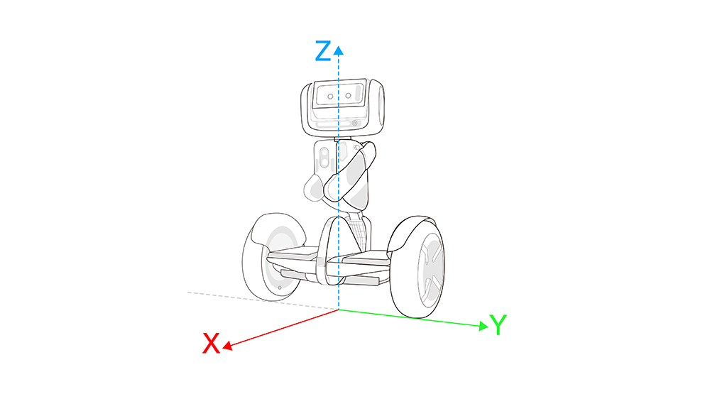
( Robot Reference Frame )
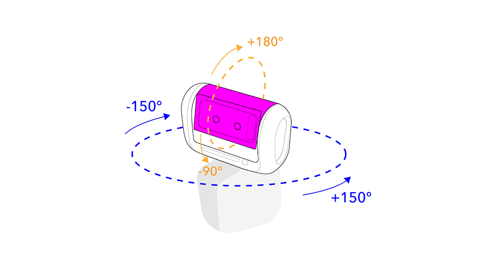
( Head Yaw Pitch Angle Range )
Head
On the head of Loomo, there are two dimensions that can be controlled: Pitch and Yaw, which support the Smooth Tracking and Lock mode:
- The Smooth Tracking mode: In this mode, the Pitch axis of the head is stable and can effectively filter the impact of the body. The Yaw axis can rotate following the base. In this state, the head can be controlled by setting the angle using the base as the reference frame.
- The Lock mode: In this mode, the Pitch axis on the head is stable and can effectively filter the impact of the body. The Yaw axis points to a certain direction in the world coordinate system. For a fixed point, this model can be used to achieve stable shooting results. In this mode, you can control the head orientation by setting the head rotation velocity.
- The Emoji mode: This mode is used only in the Emoji SDK.
See the following sample code:
Before using it, you need to initialize the Head instance and bind the service:
// bindService, if not implemented, the Head API will not work.
mHead.bindService(getApplicationContext(), mServiceBindListener);
Set to the Smooth Tracking mode and control the head's position:
mHead.setMode(Head.MODE_SMOOTH_TACKING);

mHead.setWorldPitch((float) Math.PI);
mHead.setWorldYaw((float) Math.PI);
Set to the Lock mode and control the head's velocity:
mHead.setMode(Head.MODE_ORIENTATION_LOCK);

mHead.setYawAngularVelocity((float) Math.PI);
mHead.setPitchAngularVelocity((float) Math.PI);
A new method is added to change the head light mode:
mHead.setHeadLightMode(0);Note: A different command must be sent before the flashing command will be accepted.
Note: The value is ranged from 0 to 13 and the default vaule in developer mode is 0.
Base
The base of Loomo is built on the latest two-wheel self-balancing technology. By using the Base SDK, developers can control the base's linear and angular velocity. While controlling the robot base, it is required to set it at a continuous velocity. The robot base will stop moving if there is no velocity setting within 700 ms.
Before using it, you need to initialize the Base instance and bind the service:
mBase.bindService(getApplicationContext(),mServiceBindListener);Odometry
Odometry provides an estimated robot pose (x, y, orientation) relative to a starting pose. The origin of the coordinate frame is the x, y, z center of the base. The X-axis is pointed to the front of the robot, y to the left, and z perpindicular to the ground. Theta follows the Right Hand Rule (counter-clockwise). It updates every 50ms. For a well-calibrated robot, the accuracy of the odometry is 99% - 99.9%.
Call getOdometryPose() to get the Pose at a certain time(microseconds). We only buffed the data for a few seconds.
mBase.getOdometryPose(System.currentTimeMillseconds() * 1000);If you want to get the latest Pose, you can pass -1 to this API
mBase.getOdometryPose(-1);Setting Loomo's Point of Origin
Odometry is very useful, but when you try to make Loomo walk from point A to point B, you have to remap these points from your virtual map to odometry map. So we provided an API which can set the starting point. It is important to know that once you set the starting point, the getOdometryPose() will return Pose2D based on its previous starting point. And before you set the starting point again, please make sure to call cleanOriginalPoint() to clear the previous starting point.
mBase.cleanOriginalPoint();
Pose2D pose2D = mBase.getOdometryPose(-1);
mBase.setOriginalPoint(pose2D);

mBase.addCheckPoint(1f, 0, (float) (Math.PI /2));
mBase.addCheckPoint(1f, 1f, (float) (Math.PI));
mBase.addCheckPoint(0f, 1f, (float) (-Math.PI /2));
mBase.addCheckPoint(0, 0, 0);
setOriginalPoint() sets the wheel odometry to any input Pose2D and starts to accumulate there.
Base Control Modes
There are three different modes for Loomo's base:
*CONTROL_MODE_RAW: In this mode, you can manipulate Loomo's base by directly setting the linear and angular velocities.
*CONTROL_MODE_NAVIGATION: In this mode, you can order Loomo to move to a certain point by adding checkpoints. Loomo will try to go over each of these checkpoints one by one. The accuracy is a range of 0.25 meters.
*CONTROL_MODE_FOLLOW_TARGET: This mode is designed for the "follow me" scenario. In this mode, Loomo will try to move to a point by receiving a distance and direction relative to itself. The add checkpoint API is not usable, so call update target instead. The update target API will make the robot move to the latest point.
Set the current linear velocity and angular velocity of the robot under CONTROL_MODE_RAW:
mBase.setControlMode(Base.CONTROL_MODE_RAW);
mBase.setLinearVelocity(1.0f);
mBase.setAngularVelocity(0.15f);
Add a few checkpoints to the robot under CONTROL MODE NAVIGATION:
mBase.setControlMode(Base.CONTROL_MODE_NAVIGATION);

mBase.setOnCheckPointArrivedListener(new CheckPointStateListener() {
    @Override
    public void onCheckPointArrived(CheckPoint checkPoint, final Pose2D realPose, boolean isLast) {

    }

    @Override
    public void onCheckPointMiss(CheckPoint checkPoint, Pose2D realPose, boolean isLast, int reason) {

    }
});

mBase.addCheckPoint(1f, 0, (float) (Math.PI /2));
mBase.addCheckPoint(1f, 1f, (float) (Math.PI));
mBase.addCheckPoint(0f, 1f, (float) (-Math.PI /2));
mBase.addCheckPoint(0, 0, 0);
If you want to stop the robot before it goes over all of the checkpoints, set the base to CONTROL MODE RAW.
Make the robot follow somebody under CONTROL MODE FOLLOW TARGET:
mBase.setControlMode(Base.CONTROL_MODE_FOLLOW_TARGET);

while(someConditionIsTrue) {
    Person person = getPersonFromDTS();
    if (person.getDistance() > 0.35 && person.getDistance() < 5) {
        mBase.(person.getDistance() - 1.2, person.getTheta());
    }
}
In some special cases, a third wheel is added to enhance the stability of Loomo. After calling setCartMode(true), Loomo will stop self-balancing but still accept speed commands.
// stop self-balancing
mBase.setCartMode(true);
mBase.setLinearVelocity(1.0f);
mBase.setAngularVelocity(0.15f);

// recover self-balancing
mBase.setCartMode(false);Note: There is a known issue when using the CONTROL MODE NAVIGATION. The onCheckPointArrived() callback is supposed to call when Loomo arrives at each checkpoint. However, an existing bug makes it such that Loomo will be called only when it arrives at the last checkpoint.
Tips on controlling Loomo
There is only one thing about Loomo that needs to be understood. It only has 2 wheels as we have only 2 legs, so it has limitations like all Segways: "maintaining balance is its main priority".
Because Loomo always needs to maintain self-balance, when it wants to accelerate, it will first tilt its body, and then move. Correspondingly, when Loomo wants to slow down, it will first tilt its body in the opposite direction. So, there is always a delay in controlling Loomo.
Tips for Navigation Mode:
Loomo cannot walk sideways. If the target point is set to the side of Loomo, it will walk in an arc to reach this point.
Similar to driving a car, Loomo will slow down when it turns, and it has been handled by the SDK internally. Just try this method:
public CheckPoint addCheckPoint(float x, float y)If you want a curved path for turning, use this method:
public CheckPoint addCheckPoint(float x, float y, float theta)
Loomo will arrive at the point (x,y) and then turn to the orientation at theta. (The value of theta can only range from -PI to PI)
Under the Raw Mode, the maximum adjustible speed is 0.35m/s. But under the Navigation Mode, Loomo has been set to go faster.
The navigation mode allows Loomo to easily move to a certain point. Accuracy is about 0.25 meters. So if you set a point to less than 0.25 meters away from Loomo, it will not move.
Tips for Follow Mode:
The updateTarget() method must be called continuously. If it is not called within 400ms, Loomo will stop moving. Therefore, if the frequency of the call is just slightly more than 400ms, Loomo will jitter.
Do not pass the target distance and orientation detected in DTS directly to the updateTarget() method, which will cause Loomo to hit the target. The correct way is to subtract the distance between Loomo and the target from the total distance.
For example, if you want Loomo to follow you with a space of one meter:
 float expect_space = 1.0f;
 float distance = distance_from_loomo_to_target - expect_space;
 float angle_from_loomo_to_target;
 updateTarget(distance, angle);
Visual Localization System
Visual localization system is a better alternative for navigation than Odometry. VLS is based on depth images to calculate coordinate data, which has higher accuracy than Odometry.
// set base control mode
mBase.setControlMode(Base.CONTROL_MODE_NAVIGATION);
// start VLS
mBase.startVLS(true, true, new StartVLSListener() {
        @Override
        public void onOpened() {
              // set navigation data source
              mBase.setNavigationDataSource(Base.NAVIGATION_SOURCE_TYPE_VLS);
              mBase.cleanOriginalPoint();
              PoseVLS poseVLS = mBase.getVLSPose(-1);
              mBase.setOriginalPoint(poseVLS);
              mBase.addCheckPoint(1f, 0);
              mBase.addCheckPoint(1f, 1f);
              mBase.addCheckPoint(0f, 1f);
              mBase.addCheckPoint(0, 0);
        }

        @Override
        public void onError(String errorMessage) {
              Log.d(TAG, "onError() called with: errorMessage = [" + errorMessage + "]");
        }
});Note: Since VLS is used for navigation, the Base control mode should be set to Base.CONTROLMODENAVIGATION.
Note: The navigation data source should be set to Base.NAVIGATIONSOURCETYPE_VLS, or else VLS will not work at all.
Download the sample code of Locomotion SDK.
Download the Track Imitater sample code of Phone.
Download the Track Imitater sample code of Robot.
Download the VLS sample code of Robot.
See the detailed Locomotion SDK document.
Sensor
The Sensor SDK is a collection of APIs, which can be used to get data from many of Loomo's sensors. These built-in sensors can detect events or changes in quantities.
The ultrasonic sensor is designed to detect obstacles and avoid collisions. The ultrasonic sensor is mounted in the front of Loomo, with a detection distance from 250 millimeters to 1500 millimeters and an angle beam of 40 degrees.
Loomo also has two infrared sensors to observe road condition changes in order to travel smoothly.
Before using the SDK, you need to initialize the Sensor instance and bind the service:
mSensor = Sensor.getInstance();
mSensor.bindService(getApplicationContext(), new ServiceBinder.BindStateListener() {
        @Override
        public void onBind() {
            Log.d(TAG, "sensor onBind");

        }

        @Override
        public void onUnbind(String reason) {

        }
    });
Getting different of sensor data:
SensorData mInfraredData = mSensor.querySensorData(Arrays.asList(Sensor.INFRARED_BODY)).get(0);
float mInfraredDistanceLeft = mInfraredData.getIntData()[0];
float mInfraredDistanceRight = mInfraredData.getIntData()[1];

SensorData mUltrasonicData = mSensor.querySensorData(Arrays.asList(Sensor.ULTRASONIC_BODY)).get(0);
float mUltrasonicDistance = mUltrasonicData.getIntData()[0];

SensorData mHeadImu = mSensor.querySensorData(Arrays.asList(Sensor.HEAD_WORLD_IMU)).get(0);
float mWorldPitch = mHeadImu.getFloatData()[0];
float mWorldRoll = mHeadImu.getFloatData()[1];
float mWorldYaw = mHeadImu.getFloatData()[2];

SensorData mHeadPitch = mSensor.querySensorData(Arrays.asList(Sensor.HEAD_JOINT_PITCH)).get(0);
float mJointPitch = mHeadPitch.getFloatData()[0];

SensorData mHeadYaw = mSensor.querySensorData(Arrays.asList(Sensor.HEAD_JOINT_YAW)).get(0);
float mJointYaw = mHeadYaw.getFloatData()[0];

SensorData mHeadRoll = mSensor.querySensorData(Arrays.asList(Sensor.HEAD_JOINT_ROLL)).get(0);
float mJointRoll = mHeadRoll.getFloatData()[0];

SensorData mBaseTick = mSensor.querySensorData(Arrays.asList(Sensor.ENCODER)).get(0);
int mBaseTicksL = mBaseTick.getIntData()[0];
int mBaseTicksR = mBaseTick.getIntData()[1];

SensorData mBaseImu = mSensor.querySensorData(Arrays.asList(Sensor.BASE_IMU)).get(0);
float mBasePitch = mBaseImu.getFloatData()[0];
float mBaseRoll = mBaseImu.getFloatData()[1];
float mBaseYaw = mBaseImu.getFloatData()[2];

SensorData mPose2DData = mSensor.querySensorData(Arrays.asList(Sensor.POSE_2D)).get(0);
Pose2D pose2D = mSensor.sensorDataToPose2D(mPose2DData);
float x = pose2D.getX();
float y = pose2D.getY();
float mTheta = pose2D.getTheta();
float mLinearVelocity = pose2D.getLinearVelocity();
float mAngularVelocity = pose2D.getAngularVelocity();

SensorData mWheelSpeed = mSensor.querySensorData(Arrays.asList(Sensor.WHEEL_SPEED)).get(0);
float mWheelSpeedL = mWheelSpeed.getFloatData()[0];
float mWheelSpeedR = mWheelSpeed.getFloatData()[1];Note: The unit of Distance is the millimeter. The unit of Angle is the radian. The unit of LinearVelocity is meters per second. The unit of AngularVelcity is radians per second. The unit of LeftTicks and RightTicks is Tick, which equals one centimeter when the tires are properly inflated.
Note: There is a known issue that when the distance between the obstacle and the ultrasonic sensor is less than 250 millimeters, an incorrect value may be returned.
Note: When you call robotTotalInfo.getHeadWorldYaw().getAngle() to get the value of WorldYaw, it will always returns 0.0f since it is not yet supported in the current version.
Transformation Frames "Tf"
The Tf SDK provides developers with the AlgoTfData class. With this, one can obtain spatial and rotational coordinates of each of Loomo's stored coordinate frames, e.g. the platform camera frame, the base pose frame, and the odometry origin frame.
One must obtain the Tf data by using a method in the Sensor SDK, "getTfData". In the input, one must use each of Loomo's frames in a pairwise fashion, first indicating the target frame and then the source frame. This gives the data of the target frame with respect to the source frame. In the following code, the Tf data of the platform camera frame is retrieved with respect to the base pose frame. -1 means to retrieve data from the most recent time stamp.
AlgoTfData Tf;
Tf = mSensor.getTfData(Sensor.PLATFORM_CAM_FRAME, Sensor.BASE_POSE_FRAME, -1, 100);
As mentioned before, the Tf data provides spatial and rotational coordinates. The spatial coordinates are contained in the "t" variable of the type Translation. The rotational coordinates are contained in the "q" variable of the type Quaternion. One is able to retrieve the ptich, yaw, and roll data from the Quaternion class provided in the SDK.
Tf.t.x; // the x-coordinate of the camera frame w.r.t the base frame
Tf.t.y; // the y-coordinate of the camera frame w.r.t the base frame
Tf.t.z; // the z-coordinate of the camera frame w.r.t the base frame
Tf.q; // the quaternion of the camera frame w.r.t the base frame
Tf.q.getYawRad();
Tf.q.getPitchRad();
Tf.q.getRollRad();
With this information, one has the ability to calculate other reference frames with respect to the robot using the Translation and Quaternion classes. The following code demonstrates the operations to do the necessary calculations for rotation or translation transformations.
//initialization
Quaternion rotation;
rotation = new Quaternion(0,0,0,0);
Translation translation;

//giving values
rotation.setEulerRad((float)Math.PI/2,0,0);
translation = new Translation (0,1,0);

//operations
Tf.q.mul(rotation); //quaterion multiplication, returns quaternion
Tf.q.quaternionRotate(translation); //quaternion and translation multiplication, returns translation
Emoji
The Emoji SDK is a framework that allows Loomo to coordinate and play emotions, sounds, and actions. This allows the robot to be lifelike. Using Loomo's default expression library, with just a few lines of code, makes Loomo "look down," "look up," or "look around".
In this Emoji version, we provide 16 different emojis.
The following code demonstrates how to use the Emoji SDK.
First, put the EmojiView in your layout:
<com.segway.robot.sdk.emoji.EmojiView
     android:id="@+id/face"
     android:layout_width="match_parent"
     android:layout_height="match_parent">
</com.segway.robot.sdk.emoji.EmojiView>
Second, init the Emoji. The HeadControlManager is a class implements HeadControlHandler. In this class we use the Head SDK, make an interface to let the Emoji control the robot head. And it is important to set the robot head to Emoji mode before the animation starts.
Emoji mEmoji;
HeadControlManager mHandcontrolManager;

mEmoji = Emoji.getInstance();
mEmoji.init(this);
mEmoji.setEmojiView((EmojiView) findViewById(R.id.face));

HeadControlManager mHandcontrolManager = new HeadControlManager(this);
mEmoji.setHeadControlHandler(mHandcontrolManager);
Finally, make an emoji.
mEmoji.startAnimation(RobotAnimatorFactory.getReadyRobotAnimator(BehaviorList.TURN_AROUND), new EmojiPlayListener() {
                            @Override
                            public void onAnimationStart(RobotAnimator animator) {

                            }

                            @Override
                            public void onAnimationEnd(RobotAnimator animator) {

                            }

                            @Override
                            public void onAnimationCancel(RobotAnimator animator) {

                            }
                        });
There is a small sample on how to use the Emoji SDK. In this sample, the user can control the robot to make different emojis by voice command. You can get the source code here:
Download the sample code of the EmojiVoice Sample.
Connectivity
The Connectivity service helps developers transfer messages and small amounts of data (less than 1MB at a time) between mobile phones and Loomo through a WiFi network. This service can greatly simplify the development of applications which use mobile phones to interact with Loomo.
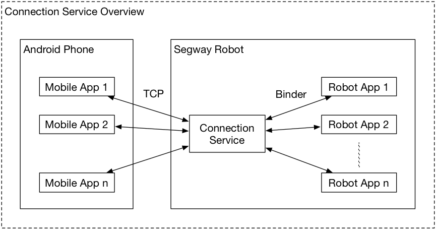
The Connectivity Service is running within Loomo and acts as the message processing center. The application on the mobile phones connects to the service through TCP, and the application on Loomo connects to the service through Binder.
Before using the service, you need to understand the following two classes:
- MessageRouter: the entry class on the outermost layer of the Connectivity service. You can use the instance of this class to connect to the service.
- MessageConnection: When both of the applications of Loomo and the mobile phone connect to the service through the MessageRouter, MessageRouter returns a MessageConnection instance through the callback. Developers can use it to communicate messages between the mobile phone and Loomo applications.
In addition, for safety concerns, the Connectivity Service defines the connection permissions using the predefined fields in AndroidManifest. Connection is performed only when the definitions match.
For example, if the package name of the phone app is: com.segway.connectivity.sample.phone, and the package name on the robot application is: com.segway.connectivity.sample.robot. The following needs to be defined in AndroidManifest of the mobile phone application:
<meta-data android:name="packageTo1" android:value=" com.segway.connectivity.sample.robot "></meta-data>The following needs to be defined in AndroidManifest of the mobile robot application:
<meta-data android:name="packageTo1" android:value=" com.segway.connectivity.sample.phone "></meta-data>The Connectivity SDK has two parts: the robot side SDK and the mobile phone side SDK. The two sides need to be integrated respectively.
Code sample on the robot side
Initialize the SDK and bind to the Connectivity Service:
//get RobotMessageRouter
mRobotMessageRouter = RobotMessageRouter.getInstance();
//bind to connectivity service in robot
mRobotMessageRouter.bindService(this, mBindStateListener);
If the binding is successful, you need to register the Connectivity Service. The Connectivity Service checks the connection information in the AndroidManifest of the current application and performs a connection match:
//register MessageConnectionListener in the RobotMessageRouter
mRobotMessageRouter.register(mMessageConnectionListener);
While registering, a MessageConnectionListener instance needs to be input, which is used to notify the developers when there is a new connection.
After the application on the mobile phone side is started and connected to the Connectivity Service, the SDK notifies that the connection is established through a callback function. You can set the ConnectionStateListener to listen to the connection and disconnection of MessageConnection and receive messages by setting the MessageListener instance.
@Override
public void onConnectionCreated(final MessageConnection connection) {
    Log.d(TAG, "onConnectionCreated: " + connection.getName());
    mMessageConnection = connection;
    try {
        mMessageConnection.setListeners(mConnectionStateListener, mMessageListener);
    } catch (Exception e) {
        e.printStackTrace();
    }
}
The messages sent or received can be either String and byte[].
Note: The Connectivity Service is designed to transfer small amounts of data. Therefore, there are strict limits on the data size: the size of the string characters and the class instance cannot be more than 1MB.
Send String:
mMessageConnection.sendMessage(new StringMessage("Hello world!"));Send byte:
mMessageConnection.sendMessage(new BufferMessage(bytebuffer.array()));Receive messages:
private MessageConnection.MessageListener mMessageListener = new MessageConnection.MessageListener() {
    @Override
    public void onMessageReceived(final Message message) {
        // message received
    }
};
Code sample on the mobile side
Note: Before connecting, make sure Loomo and the mobile phone are on the same local area network. The current edition needs the mobile phone to know the IP address of Loomo explicitly.
Initialize the SDK, set the IP address of Loomo, and connect to the Connectivity Service on Loomo's side:
mMobileMessageRouter = MobileMessageRouter.getInstance();

//robot-sample, you can read the IP from the robot app.
mMobileMessageRouter.setConnectionIp(myRobotIPAddress);

//bind the connectivity service in robot
mMobileMessageRouter.bindService(this, mBindStateListener);
The method to retrieve the MessageRouter instance, get the MessageConnection instance, and send/receive messages are the same for both the phone and the robot.
Download the sample code of the Connectivity Sample (Robot).
Download the sample code of the Connectivity Sample (Phone).
Download the sample code of the Track Imitater sample (Robot).
Download the sample code of the Track Imitater sample (Phone).